


BS 4235-2 Metric Woodruff Keys and Keyways
BS 4235-2 specifies metric Woodruff keys and their keyways. The drawing identifies the key width, segment height and nominal disc diameter.
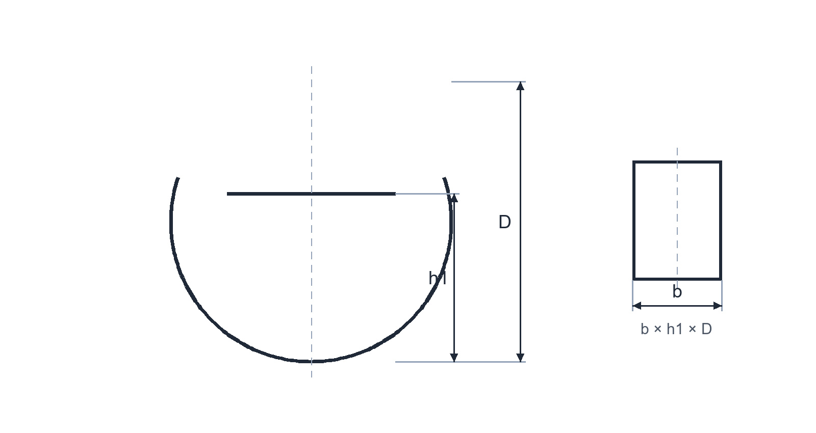
Selected Woodruff key sizes
| Key size b × h1 × D (mm) | Width b (mm) | Height h1 (mm) | Diameter D (mm) |
|---|---|---|---|
| 1.0 × 1.4 × 4 | 1.0 | 1.4 | 4 |
| 1.5 × 2.6 × 7 | 1.5 | 2.6 | 7 |
| 2.0 × 2.6 × 7 | 2.0 | 2.6 | 7 |
| 2.0 × 3.7 × 10 | 2.0 | 3.7 | 10 |
| 2.5 × 3.7 × 10 | 2.5 | 3.7 | 10 |
| 3.0 × 5.0 × 13 | 3.0 | 5.0 | 13 |
| 3.0 × 6.5 × 16 | 3.0 | 6.5 | 16 |
| 4.0 × 6.5 × 16 | 4.0 | 6.5 | 16 |
| 4.0 × 7.5 × 19 | 4.0 | 7.5 | 19 |
| 5.0 × 6.5 × 16 | 5.0 | 6.5 | 16 |
| 5.0 × 7.5 × 19 | 5.0 | 7.5 | 19 |
| 5.0 × 9.0 × 22 | 5.0 | 9.0 | 22 |
| 6.0 × 9.0 × 22 | 6.0 | 9.0 | 22 |
| 6.0 × 10.0 × 25 | 6.0 | 10.0 | 25 |
| 8.0 × 11.0 × 28 | 8.0 | 11.0 | 28 |
| 10.0 × 13.0 × 32 | 10.0 | 13.0 | 32 |
Reference note: Dimensions are nominal millimetres from the BS 4235-2 metric Woodruff-key schedule. The standard also specifies keyway geometry, fits and tolerances; use the matching shaft and hub schedule for a complete design.